

Hey! Guys,
network engineers deal with switches every day. Especially in large - scale networks, various configuration requirements can be really frustrating. Many brothers often say in the background, "I understand the principles and have memorized the commands, but when it comes to actually configuring a complex network, I still don't feel confident."
Don't worry. Today, we'll take an example of a large - scale network to talk about it. It is said that if you thoroughly understand this case, most of the problems in switch VLAN configuration can be solved, and independent configuration is basically a piece of cake.
Can ing be made between different network segments in the same VLAN?
For more information, please scan the WhatsApp QR code below to contact customer service.

01 Let's look at the configuration background and purpose
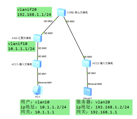
In the enterprise, security and management are of great importance. Therefore, a VLAN 20 is specifically allocated for the server, and users use VLAN 10. There are three - layer switches including access, aggregation, and core switches between these two VLANs. The access switch is a layer - 2 switch, while the aggregation and core switches are layer - 3 switches. Now, how can we enable communication between users and the server?
The goal is clear: configure switches to enable cross-device communication between different VLANs.
02 Configuration ideas should be clarified first
To put it bluntly, it is to use static routing to make different network segments recognize the path, and the steps are roughly as follows:
VLAN is divided by interface on the access switch to lay a solid foundation for two-layer communication;
Create VLANIF10 on the aggregation switch (AGG) as the gateway for users; create VLANIF20 on the core switch (CORE) as the gateway for servers.
There must be a path between the aggregate and the core, so static routes are assigned to both sides: the AGG knows the path to VLANIF20 and the CORE knows the path to VLANIF10.
03 Step by step, configuration details are broken down
1. Connect to ACC1 switch (user side)
Change the name first for easy identification:
1 system-view
2 [HUAWEI] sysname ACC1
Create VLAN 10 and partition the interface that connects the user:
1 [ACC1] vlan batch 10
2 [ACC1] interface gigabitethernet 0/0/1
3 [ACC1-GigabitEthernet0/0/1] port link-type access
4 [ACC1-GigabitEthernet0/0/1] port default vlan 10
5 [ACC1-GigabitEthernet0/0/1] quit
The interface connected to the hub switch must allow traffic from VLAN 10 to pass through, so use trunk
1 [ACC1] interface gigabitethernet 0/0/2
2 [ACC1-GigabitEthernet0/0/2] port link-type trunk
3 [ACC1-GigabitEthernet0/0/2] port trunk allow-pass vlan 10
4 [ACC1-GigabitEthernet0/0/2] quit
2. Connect to ACC2 switch (server side)
In the same way, rename first and create VLAN 20:
1 system-view
2 [HUAWEI] sysname
3 ACC2[ACC2] vlan batch 20
The interface connected to the server is assigned to VLAN 20:
1 [ACC2] interface gigabitethernet 0/0/1
2 [ACC2-GigabitEthernet0/0/1] port link-type access
3 [ACC2-GigabitEthernet0/0/1] port default vlan 20
4 [ACC2-GigabitEthernet0/0/1] quit
Use trunk for the interface connecting to the core switch and pass through VLAN 20:
1 [ACC2] interface gigabitethernet 0/0/2
2 [ACC2-GigabitEthernet0/0/2] port link-type trunk
3 [ACC2-GigabitEthernet0/0/2] port trunk allow-pass vlan 20
4 [ACC2-GigabitEthernet0/0/2] quit
3. Aggregation switch AGG (user-side gateway)
After the name is changed, create VLAN 10 (for users) and VLAN 30 (for core interconnection):
1 system-view
2 [HUAWEI] sysname AGG
3 [AGG] vlan batch 10 30
Interface configuration should keep up:
The port connected to ACC1 uses trunk to transparently transmit VLAN 10: 1
1 [AGG] interface gigabitethernet 0/0/2
2 [AGG-GigabitEthernet0/0/2] port link-type trunk
3 [AGG-GigabitEthernet0/0/2] port trunk allow-pass vlan 10
4 [AGG-GigabitEthernet0/0/2] quit
Connect to the port of the core switch and use trunk to transmit VLAN 30:
1 [AGG] interface gigabitethernet 0/0/3
2 [AGG-GigabitEthernet0/0/3] port link-type trunk
3 [AGG-GigabitEthernet0/0/3] port trunk allow-pass vlan 30
4 [AGG-GigabitEthernet0/0/3] quit
Next is the key —— Build the gateway interface:
1 Use VLANIF10 as the user gateway and configure the IP 10.1.1.1/24:
2 [AGG] interface vlanif 10
3 [AGG-Vlanif10] ip address 10.1.1.1 24
4 [AGG-Vlanif10] quit
VLANIF30 is used to connect to the core and is equipped with IP 10.10.30.1/24 (do not conflict with other IP addresses):
1 [AGG] interface vlanif 30
2 [AGG-Vlanif30] ip address 10.10.30.1 24
3 [AGG-Vlanif30] quit
Finally, static routing is configured so that users can find the server subnet (192.168.1.0/24) and the next hop points to the core VLANIF30 (10.10.30.2):
1 Plaintext
2 [AGG] ip route-static 192.168.1.0 255.255.255.0 10.10.30.2
4. After renaming the core switch CORE (server - side gateway),
create VLAN 20 (for servers) and VLAN 30 (for interconnection with aggregation):
1 system-view
2 [HUAWEI] sysname CORE
3 [CORE] vlan batch 20 30
Interface configuration:
Connect to port ACC2, trunk transparent VLAN 20:
1 [CORE] interface gigabitethernet 0/0/2
2 [CORE]-GigabitEthernet0/0/2] port link-type trunk
3 [CORE]-GigabitEthernet0/0/2] port trunk allow-pass vlan 20
4 [CORE]-GigabitEthernet0/0/2] quit
The port connected to the aggregation, trunk passes through VLAN 30:
1 [CORE] interface gigabitethernet 0/0/3
2 [CORE-GigabitEthernet0/0/3] port link-type trunk
3 [CORE-GigabitEthernet0/0/3] port trunk allow-pass vlan 30
4 [CORE-GigabitEthernet0/0/3] quit
Create gateway interface:
Use VLANIF20 as the server gateway and configure the IP address 192.168.1.1/24:
1 [CORE] interface vlanif 20
2 [CORE-Vlanif20] ip address 192.168.1.1 24
3 [CORE-Vlanif20] quit
VLANIF30 connected to the converged interconnection with IP 10.10.30.2/24:
1 [CORE] interface vlanif 30
2 [CORE-Vlanif30] ip address 10.10.30.2 24
3 [CORE-Vlanif30] quit
With static routing, the server can find the user's network segment (10.1.1.0/24), and the next hop is directed to the aggregation
1 VLANIF30(10.10.30.1):
2 [CORE] ip route-static 10.1.1.0 255.255.255.0 10.10.30.1
04 How to verify after configuration?
User PC is configured with IP 10.1.1.2/24, and the gateway is set to 10.1.1.1 (VLANIF10 of AGG);
The server has IP 192.168.1.2/24, and the gateway is set to 192.168.1.1 (CORE VLANIF20).
At this point, both sides ping each other. If it works, it means it's done.
05 Finally, let's wrap up the key points
The core of this case is to use the VLANIF interface as a gateway and static routing to connect cross-device network segments. VLANIF30 acts like a bridge, connecting the aggregation layer and core layer, allowing VLAN 10 and VLAN 20 to communicate across the river.
Remember, for cross-device communication between different network segments, only layer 2 VLAN is not enough, and layer 3 routing must be relied on. Static routing configuration is simple and suitable for stable topology networks, but the disadvantage is that the network needs to be manually modified when it changes, so dynamic routing protocol may be needed in complex scenarios.
For more Huawei Switch Large Network Configuration resources, follow the Facebook account & youtube account: Thinkmo Dumps